

Introduction
In this article we will discuss the different manufacturing processes used to create external threads.
There are two methods that can be used to produce an external thread, these are rolling (a deformative process) and cutting (a subtractive process).
We will look at these manufacturing process' and the advantages and disadvantages of each.
Rolled Threads
When a thread is created by rolling, it uses a process of cold forming, where the blank piece is passed between either hardened steel plates or round dies.
These dies will have either the thread pitch or a standard groove machined into their face, depending on the particular thread rolling type and process being used, and as the blank passes over them, the large forces applied by the dies to the blank result in the forming of the thread.
Gears and knurling can also be achieved in the same way as rolled threads by simply using different dies.
Due to the fact that the blank is under pressure and rolling is a cold forming process, the grain of the material flows in multiple directions, as shown in Figure 1, which results in improved strength properties.
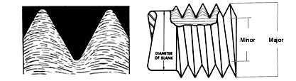
Figure 1 - Grain Flow Post Rolling - (Image courtesy of Atlanta Rod and Manufacturing)
Thread rolling is a very popular method for the manufacture of fasteners, especially on high volume runs.
Industries such as oil and gas, aerospace and transport often specify the use of rolled threads for safety critical components for reasons that we will see further on in this article.
Types of Thread Rolling
There are four types of thread rolling methods which are used on either a dedicated thread rolling machine or as an attachment piece of tooling. The four methods and where they are used are show in the table below:
| Rolling Method | Typical Applications |
| 2 Die Cylindrical | Used on dedicated machines and tooling attachment. |
| 3 Die Cylindrical | Used on dedicated machines and tooling attachment. |
| Flat Die | Used on dedicated machines. |
| Planetary Die | Used on dedicated machines. |
Thread Rolling Machine
Flat Die Thread Rolling Machine
A flat die thread rolling machine consists of four main parts, These are two flat dies, one which is fixed and one which is moved backwards and forwards, usually by a crank type mechanism, a conductor bar and a pusher arm.2 Die Cylindrical Thread Rolling Machine
These machines can come in three variations. Infeed, thrufeed and combination infeed/thrufeed. All variations come with a work rest which helps position the blank at the correct height between the dies.
Infeed machines consist of two parallel dies which are rotated at the same speed and in the same direction. One die is fixed and the other moves laterally. This laterally moving die is also why this process is sometimes also known as plunge feed.
The lateral movement can be adjusted to set the final diameter of the rolled workpiece and the thread pitch is machined into the die, providing an extremely accurate thread. Just like in the flat die machine, the rolling process relies on friction to rotate the blank.
As the length of thread that can be rolled is limited by the overall width of the dies being used, infeed (plunge) thread rolling is most often used for short threaded lengths and bolts.
The length of the thread being created has to be shorter than the working face of the die. To ensure the die being used is long enough and sufficient clearance is left at each end, the following calculation can be use as a general guide.
Thread Rolling Die Working Face = Overall Thread Length + (2.5 x Thread Pitch)
Just like the infeed process, the thrufeed process uses parallel dies that rotate at the same speed and direction. However, unlike the infeed dies, the thrufeed dies do not have the thread pitch machined into them. They have a standard groove profile.
To achieve the thread pitch that is required on the blank, the angle of the axis of the dies are adjusted by the thread pitch angle. This adjustment also results in the axial movement of the blank at a distance of one pitch per revolution and the removal of the requirment for the second die to be laterally adjustable.
The thrufeed process is particularly suited to long threaded sections such as studding and leadscrews. It should be noted that on larger threads, more than one pass may be required to produce the completed thread.
A combination machine allows for both infeed and thrufeed process' on the same machine.
The video below provides a good example of a combination infeed/thrufeed thread rolling machine:
3 Die Cylindrical Thread Rolling Machine
As with a 2 die cylindrical thread rolling machines, a 3 die thread rolling machine can come in one of the three variations as mentioned in the previous section.
Two of the three dies are fixed and the third can either move laterally or vertically depending on the particular machines layout. This machine is particularly useful for long threaded components such as leadscrews.
The below video shows a 3 die thread rolling machine in action:
Planetary Thread Rolling Machine
The planetary thread rolling machine is similar to the flat die thread rolling machine in terms of the way in which the blanks are fed into the dies.
There are normally two dies used on this machine. There is a circular die which rotates and there is a curved die that is fixed. The curved die is also sometimes know as a curved segment die or simply as a segment. Some machines can have multiply segments mounted on them around the circular die.
Very high production rates are achievable using planetary thread rolling.
The below video shows a planetary thread rolling machine in action:
Thread Rolling Attachment
Another option for the creation of rolled threads is to use a thread rolling attachment for CNC machines. There are two types of thread rolling attachments which are tangential thread rolling and axial thread rolling heads.
Tangential Thread Rolling
The tangential thread rolling attachment is particularly useful for the creation of threads behind a collar due to the collar preventing the axial thread attachment from reaching the location to be threaded.
Similar to this, when a rolled thread is required close to a collar, the collar may prevent the creation of the full thread if using an axial thread rolling attachment. Typically, tangential thread rolling allows for a thread to be within 1x the thread pitch of the shoulder face.
Tangential thread rolling attachments are not suitable for long threads as the thread lengths that can be created are limited to the width of the dies fitted.
Threads of up to 42mm diameter and 31mm long are typically achievable using tangential thread rolling attachments.
The dies have the thread to be created machined or ground into them as the dies engage with the workpiece laterally with no axial movement of either the attachment or workpiece during the process.
The dies are moved towards the workpiece at a constant speed and gradually create the thread as they move towards the centre axis. Once the two dies are inline with the workpiece centre axis, the thread is complete.
The threads on hydraulic fittings are often create on CNC machines using a tangential thread rolling attachment.
The video below shows a tangential thread rolling head being used to apply rolled threads to the end of a workpiece and also to a section that is in-between two shoulders.
Axial Thread Rolling
Unlike the tangential thread rolling attachment, the axial thread rolling attachment allows for long threads to be rolled, with the length being limited by the CNC machine itself rather than the attachment.
Larger diameters can also be rolled, with axial thread rolling attachments capable of diameters up to 230mm being readily available.
Just like the 2 die and 3 die thrufeed dedicated thread rolling machines, the 3 dies in an axial thread rolling attachment are mounted at an angle, with the angle at which they are mounted at being related to the pitch of the thread that is being rolled.
As with the thrufeed machines, once the workpiece engages with the dies, there is no further requirement for external forces to push the workpiece through the attachment as the resultant forces create an axial movement.
The dies are tapered so that the threads are progressively created as the workpiece passes over which means that the tool life can be improved.
The video below is very informative as it shows how an axial thread rolling head is assembled and how it operates.
Required Material Characteristics for Thread Rolling
To ensure an accurate and high quality rolled thread it is crucial that it the material that is intended to be rolled is suitable for this purpose.
In general, the harder the material, the harder it is to roll and the more of an adverse effect the operation will have on the life of the dies will be.
Issues are also encountered when rolling threads on hollow profiles due to the forces involved often causing the blank to become oval.
The table below lays out the main factors that determine a materials suitability for rolling and provides some approximate figures for each factor. If the intended material has characteristics that fall out-with these figures, then thread cutting or grinding may be the more suitable process to use.
| Suitable Material Characteristics | |
| Minimum Elongation | 12% |
| Maximum Hardness | 40 HRC |
| Maximum Tensile Strength | 1079 MPa |
If the intended material is deemed suitable for thread rolling, there are further considerations to be made as the most suitable materials for rolling will not necessary produce the highest quality thread at the end of the process compared to materials that may be harder to roll.
Also as already mentioned above, the material hardness affects the die life so this will need to be considered when making the final decision on whether the intended material is both suitable and the best material to use while also taking into consideration the components purpose and intended use. Dies sometimes come with a coating such as PVD or CVD which can improve their durability.
Thread Rolling Blanks
Just as important as material choice, the preparation of the blanks to be threaded is a crucial factor in determining the final accuracy and quality of the rolled thread. As thread rolling results in the displacement of material, the diameter of the blank is smaller than that of the final diameter of the finished rolled thread.
The blanks have to be machined or ground to tight tolerance of approximately 0.0005" (0.0127mm). It is also recommended to have a 37 degree chamfer at the each end of the section to be threaded to reduce the risk of chipping and to also produce a final chamfer of approximately 45 degree's after rolling.
CJWinter provide an excellent online calculator for the calculation of Blank Diameters.
For imperial threads, Thread Rolling Inc have a very useful Thread Rolling Blank Reference Chart.
Deciding What Thread Rolling Method To Use
As we have seen while looking at the different types of thread rolling methods and their sub processes, there are several factors which play a part in determining the suitability of a particular method. These are, but not limited to the following:
Overall Length of the Required Thread
Several thread rolling processes are limited to the length of the die working face.
Thread Diameter
Both thread rolling machines and attachments have a maximum diameter of thread that they can create.
Thread Location in Relation to Other Features on Part
Is the thread near a shoulder? Or behind a shoulder? Is the diameter of the section being rolled less than the maximum diameter of the part?
Advantages of Rolled Threads:
- More uniform surface finish.
- High speed manufacturing in large quantities.
- Enhanced thread strength (without heat treatment)
- High accuracy.
- Higher resistance to thread damage.
- Smaller body diameter, this leads to reduced overall weight.
- This weight reduction will impact the cost of steel, coating systems, surface treatments and shipping.
- No waste material.
Disadvantages of Rolled Threads:
- High initial cost of rollers and tooling. A set of dies is required for each thread type.
- Not suitable for materials with low ductility.
- Not suitable for products with cavities (such as pipes etc) due to high forces required.
- Thread size limitations.
Cut Threads
A cut thread (also called a machined thread or ground thread) is a thread that has been formed by cutting material away from the blank.
This can be achieved by using a threading die or by a single point cutting tool such as a lathe.
As this method cuts the thread into the material the material grain is also cut/sheared (as shown in Figure 2), this can affect the material yield strength unless a heat treatment is utilised post cutting.
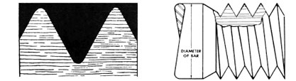
Figure 2 - Grain Flow Post Cutting - (Image courtesy of Atlanta Rod and Manufacturing)
Advantages of Cut Threads
- Cut threads can be to virtually all specification including larger diameter sizes
- Suitable for parts with cavities such as pipes etc.
- Cost effective for lower volume production.
- High accuracy achievable.
Disadvantages of Cut Threads
- Labour intensive.
- Chips caused by machining process may cause weakness in the root of thread.
- Requires a heat treatment to regain tensile strength.
- Process results in waste material.
Useful Links
Metric ThreadsMetric Coarse and Metric Fine thread sizes, pitches and required tapping drill size. |
UNC / UNF ThreadsUnified National Coarse and Unified National Fine thread sizes, threads per inch, pitches and required tapping drill size. |
References
[1] https://www.bhamfast.com/rolled-thread-vs-cut-thread-bolts/
[2] http://www.tesker.com/thread-rolling/types-thread-rolling
[3] https://tesker.com/thread-rolling/inside-thread-rolling-process
[4] https://www.atlrod.com/products/advantages-of-rolled-threads
[5] https://www.manufacturingguide.com/en/thread-rolling
[6] https://www.portlandbolt.com/technical/faqs/rolled-vs-cut-threads-bolts/
[7] https://link.springer.com/chapter/10.1007/3-540-33217-0_6
[8] https://mfgtechupdate.com/2015/08/thread-rolling-on-cnc/#:~:text=There are three main systems,Axial, Tangential and Radial.&text=The axial system comes from,to produce unlimited thread lengths.
[9] https://www.wagnercarbidesaw.com/pdf/tangential.pdf
[10] https://www.boehlerit.com/fileadmin/user_upload/PDF/Thread_rolling_systems.pdf
[11] https://eandjtooling.co.uk/products/tangential/
[12] https://www.cjwinter.com/blog/thread-rolling-fundamentals#:~:text=Other materials, like stainless steel,can compromise the thread finish.
[13] https://www.threadtools.com/uploads/pdf/technical-specs/thread-rolling.pdf
[14] https://www.thomasnet.com/articles/custom-manufacturing-fabricating/about-thread-rolling-machines-materials-and- process/
About the Author - Stuart Ferrier
Stuart Ferrier gained a BEng in Mechanical Engineering from the Napier University. Stuart has nearly 10 years experience in subsea engineering design and specialises in remote operated vehicle tooling having worked for both Fugro Subsea Ltd and Oceaneering International Inc during his career. He is a passionate engineer and strives to increase his own engineering knowledge and that of his peers and to encourage people from all walks of life to participate in all things engineering.
.jpg)
The technical advice and recommendations made in this article should not be relied or acted upon without conducting your own further investigations. The information contained within this article is intended for reference only. Please consult industry specialists and current editions of industry standards. All About Precision assumes no liability in connection with the information in this article.